
News & Updates
Explore the latest news from AttoTude

PECC 2026 - Passive Interconnects: DiAx
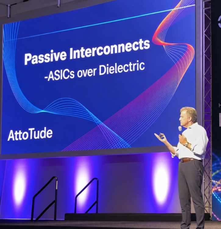
Passive Interconnects - Dave Welch, AttoTude
Passive interconnects. Why do we have to send signals over things that cost power? I want you to think about that, because there’s a presumption that every time we want to send information, we have to do that.
Transistors make more photons than optics ever did. Think about that. And what’s the choice? What’s the best choice of light source in a transmission medium? It’s not necessarily what we like in this community to call optics. A photon is an element that has released itself into a propagation media and lives by boson statistics. That’s the definition of a photon.
Okay, all that said, what I’m going to talk about today is: I’ve got electronics. They sit on my line cards. They generate signals. They’re pumping out power. They’re pumping out milliwatts. Why can’t I just put that in a new transmission media and have it go somewhere? Why do I have to upconvert it? Why do I have to go through an LED? Why do I have to go through a silicon photonics? Why do I have to go through a laser? Because if I had the right transmission media, it would go naturally.
Okay, because of time, I’m going to fly through the first few slides. They’re kind of meaningless. Guess what? Things are moving. They’re moving at an incredible rate. I’m happy to argue about wide and slow and all that stuff later, but the reality is there’s a significant fraction of business that needs to go faster, and it’s going to continue going faster. And the next stop along the line isn’t 448. The next stop is beyond that. It’s going to be 856 or some other big number. And they’re going to do it because that’s what’s necessary to make the application work.
In there, they’ve got power as a big problem. And I had a gentleman come up at an earlier conference this year and say, “Oh, it’s only 5% of the power on the interconnect.” That is actually a huge amount of problem, right? It’s not insignificant. Every watt counts.
I’m going to skip through this, but it’s basically, you know, we’ve seen this problem come many times, and I thought I’d take the absurd one, which is the subsea cable business. Just look at what happened to the repeater spacing, which went from a copper element to a dielectric transmission media, and where it is today, which is basically a convergence of: I’ve got 7,000 kilometers between my repeaters. And I deal with everything in linear optics in between there, linear optics being amplifiers, in the process. But this actually has more commonality with the problems we’re trying to deal with on the board than you might think. And it’s the choice of the transmission media that enables them to go to simpler and simpler structures.
Today, the world in the data center was built up with a bunch of ASICs, right? And those ASICs, they’ve chosen to be done in CMOS because of the volume, the reliability, the cost structure, the complexity of what you want to do. And the signal that comes out of those ASICs is a perfectly valid signal. I didn’t really need to do anything to that element to transmit it.
But for whatever reason, historical reason, I elect to transmit it directly over copper. And it’s actually not copper. The high frequency signals are actually traveling in a silver coating on top of a copper element. And if I think I want to go to longer reach than a conductor can give me, I move to a dielectric, and I think, “Oh, I’ll use glass, because that’s my most prevalent dielectric.” It’s true, and the dielectric glass is an unbelievable media. Just not at 100 gigahertz. It’s actually quite a crappy media if I’m trying to transmit something that is within the baseband of the signal generated.
I need a new dielectric. If you develop a new dielectric which is focused at the transmission bands of your electronics, well, guess what? You get the reach that you need, and you don’t have to go through upconversion. You don’t have to spend money on taking an electronic signal and transporting it to 200 terahertz in order to get to an optical fiber media. I can just go straight from that electronics media onto a dielectric directly, and it will go a significant distance for me. That’s what we’re going to talk about today.
So we went off and started this quest a couple years ago. And originally our vision was, “Well, the best transmitter of photons is a transistor. I’m going to pursue the transistor that can go as fast as possible.” And so we did all of our investigations around 700, 800 gigahertz, in there where transistors operate. And what was fascinating is we found a dielectric that truly is beautiful, with, you know, dB per meter transmission capability.
What’s shown in the photograph is a ground-signal-ground connection, which would come straight off your transistor, go through a little bit of an antenna, and that signal launches into the dielectric, and away it goes. So integrated directly into the submount that my transistor would sit on, I can go from the transistor to the dielectric and start transporting at sub-dB per meter capabilities. I get in and out of that antenna inside of three, four wavelengths of operation.
Well, EM being EM, EM really doesn’t care what frequency you operate at. You just have to scale by the wavelength. And so we started investigating this media further. And hey, you can make this media low loss all the way down. You drive it down to 50 gigahertz. Technically, you could probably drive it down to 20 gigahertz. The problem is the wavelength of light starts getting bigger and bigger and bigger in there, but as a transmission media, it works fine. And so that was interesting. And you can design it. It’s well understood from the EM model. You make it, you know, some dB per meter loss. And this particular one was designed with a cutoff frequency of the waveguide around 85 gigahertz, et cetera. But trust me, you can go much lower than that if you wish.
And then all of a sudden you say, well, let’s compare these two transmission medias. This is a very important slide. The blue curve is the transmission when I send my signal through copper in the form of a Twinax cable. And as is well understood, as the frequency gets higher, the losses get higher, and all of a sudden it becomes prohibitive. Put on there markers for 112 PAM4, 224 PAM4, and 448 PAM4 signals, and you can see that the losses at Nyquist frequencies get worse and worse and worse, and they become prohibitive.
If on that same scale I put the dB per meter loss of the dielectric, well, I want to leave that copper somewhere around 20 to 30 gigahertz. After 20 to 30 gigahertz, the dielectric is a superior transmission medium, right? And it’s beautiful because it’s flat with frequency.
I put the two of those together, and a miraculous thing happens. The Twinax loss curve collapses, and I get what we call DiAx, dielectrically enhanced Twinax: passive transmission media tuned for baseband transmission over my system. And what’s happened, as you can see, is the loss at high frequencies has plummeted from, you know, 11, 12 dB per meter to 1 dB per meter, the loss of a dielectric. At the low frequencies, well, it looks just like I’m flying around in copper, right? So in the 20 to 30 gigahertz regime, I get the characteristics as if I’m in a piece of copper. And all of a sudden my 448 signal can be viewed as equivalent to a 112 PAM4 signal, and I will get the reach that I expect at 112 PAM4, because that’s where the peak in the loss structure is.
Passive cable, same DSP, operating at 448, 2 nanometer CMOS signals, onto a passive element where the loss structure has collapsed because you’ve introduced a dielectric media inside that transmission cable for it to propagate in. 10 dB per meter reduction in loss at Nyquist.
We’ve made it. It works. There are two very interesting parts to this slide. Let’s talk about the red one first. The red one is the differential group delay, and it’s basically how much of my mode sits in the copper versus how much of my mode sits in the dielectric. And what you see is this transition region where, yes, at 20 gigahertz, I’m flying along just like I would expect, like I’m mostly in copper. And at 100 gigahertz, I’m flying along like most of my signal is in a dielectric. Right, and you can see the transition. And this is data. This isn’t a model. This is data off of cables we’ve made.
The consequence of that is that for all the stuff that’s flying along thinking it’s in the dielectric, well, its losses collapse. At Nyquist, we’re seeing over 10 dB reduction in cable loss. Right, it’s a huge benefit.
So we put that into the system. We fire up some appropriate DSPs. We predistort the input signal to accommodate that differential group delay, and we send it over a DiAx cable, and we get eye diagrams out with great SNR. It works like it’s supposed to, right?
We’ve created a new transmission media that can connect directly to your 2 nanometer CMOS sophisticated electronics. No upconversion cost. No power dissipation. Strictly a passive cable, extending the reach of this capability, and it works.
It’s being recovered in this case with a DSP. In this case, the transmission data rate is 212, but that’s because of the limited availability of high-speed DSPs. At 448, this translates into a reach of about 10 meters. DiAx cable should be able to deliver up to 10 meters passively, straight from the pre-existing SerDes chips that are out there.
And so that creates a very interesting dynamic. Before, my world consisted of two elements. It consisted of copper in the form of Twinax, where as I go faster and faster, the reach gets less and less, and all of a sudden it becomes not useful. Or I have to upconvert that signal to approximately 200 terahertz and call it an optical signal. It costs me power, it costs me money, it costs me complexity, it costs me packaging, it costs me failure rate. It bought me one thing: if I’ve got to go 500 meters, I need it. If I’ve got to go 10 meters, it’s a waste of time, right?
DiAx fills that gap. It gets you the 10 meters that you need. So if I’m going to co-package something, I’m going to co-package a passive cable before I co-package a complex active element.
I infer here, and this is for another talk later, maybe at OFC: we’ve also modeled the capability, with modifications, to push this out to 30 meters. But for right now, I’m perfectly happy at 10 meters for this table.
And that lets us walk our way through the transitions in scale-up types of applications. That means there’s plenty to get this thing going. I can get rid of my retimers. I can get rid of my conversion expense, and operate DSP to DSP, within the I/O chiplets on my switch or the I/O chiplets on my XPU.
It also lays the groundwork for the next phase, which is that it is the beautiful transmission media to feed linear optics. Okay, I have a pristine signal coming out of that transmission media when I’m co-packaged with my electronics. I have, you know, radically reduced the loss at my high frequencies, which means I’ve also radically changed all the reflection issues that come along at high frequencies. This is the beautiful precursor so that when I do want to go hundreds of meters, I’m going to go through linear optics as opposed to any type of retime event.
It’ll get implemented in several forms. Frankly, the first, easiest commercial thing to do is put together an AEC-type product. The second one, which is actually technologically easier from our end but requires more integrated engineering with the end customer, is the co-packaged element. It’s compatible with all Twinax coupling technologies out there. It presents itself as a Twinax; however, it propagates as a dielectric.
So to conclude: 10 meters, 448, no additional electronics. It is speed agnostic, because as I go out to higher and higher frequencies, my losses are flat. It’s gauge agnostic, because I’m in the dielectric at high speeds. I don’t have any P/N skew issues as I go to higher and higher speeds, because the high speeds are preferentially in the dielectric.
Let’s see. What that enables is the movement of a passive element to satisfy scale-up co-packaged configurations. It lays the groundwork for the complete solution set to be a co-packaged DiAx cable, covering the short-term scale-up capacities and transitioning to linear optics for any longer distance necessary.
So with that, I’ll wrap up. Thank you very much.

